Wh312 1 0253 12 0001302083. Moment of inertia of a rectangle.
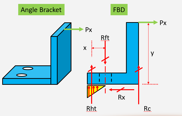
Angle Bracket Combined Loading Youtube
Click the 3D Samples dropdown.

. Design Project Calculation Sheet Checked by VK Date 3 Flange Splice Portion of load carried by each flange 05440-1028 1686 kN For M22 HSFG bolts 4 Nos in single shear Shear force bolt 16864 4215 kN Slip resistancebolt 11 u 045 u 177 8762 kN Bearing resistancebolt 22 u 9 u 650 u 10-3 1287 kN. The ladder is only 4 wide so 2 pieces of a 6 x 6 x 2 wide L bracket would work fine. L 1200plfandadesigndeadloadofw DSW 530plfincluding self-weightacrossa20ftspanThebeamwasdesignedwithfulllateralbracing C L 10Thecontractorhasrequestedauthorizationtocutanotchonthebottomface ofthebeamatoneendsupportasillustrated.
The steel angle bracket is to be supported at both ends by means of other two sets of angle brackets vertical positioned which are to be attached to I-Beams. Cantilever Bracket Calculations. Hi I am a Computer Engineer who may be in a little over my head in producing my own brackets for a shelving project I am working on.
Lets say that I would like to utilize a L 5 x 3 12 x 38 bracket to support a vertical load laying evenly on top of it. The design calculations were done for one bracket supporting the full weight of the heat exchanger rounded up to 6800 pounds. Here is a picture of the bracket that I designed and I am thinking about making it with 14 inch 6061 aluminum with the following properties.
Enter the desired parameters and click OK. One horizontal element CD 375mm long. L lkam the length of the threaded part.
A simple L shape should do. From the list select L-Bracket. One vertical element AB 330mm long with a fixing at either end to a wall.
This leads to shape of side closed L bracket Dimension of the bracket. Assuming centre of pressure 25 mm below top of cleat point A horizontal shear force on bolt due to moment due to eccentricity e 150 502 20050212522002 129 kN V2exri ri2 vertical shear force per bolt 1506 250 kN resultant shear 12922502 2813 kN. 11 shows the design result of the double L-bracket with two stress constraints and together with a pure stiffness maximization design result for comparison.
The shelf will be 30 inches deep trying it with a 025 inch thick steel bracket that is 1 inch wide supported at one end the wall and with a load of 1 pound at the far end of the shelf. One East Wacker Drive Suite 3100 Chicago IL 60601. If a leg length h 12mm is used in the equations in relevant part of the Table of bracket weld subject to direct and bending stresses above a value of τ b 198 Nmm and a value of τ s 100 Nmm 2 results with a resultant stress of Sqrt τ b 2 τ s 2 222Nmm 2Which is in general agreement with the above result.
CD is fixed at 90deg to AB 130mm from the top. Physical and Mechanical Properties Ultimate Tensile Strength psi 45000 Yield Strength psi 40000 Brinell. UsingbasicgeometrytocalculatetheresultingforceF2SeeFigure1 cos229128 29128cos302 252262 PartII.
Lg 225 2559 140 2 28295 mm sg 150 2559 140 2 20795 mm Width of the gusset plate perpendicular to the free edge Bg Lg Lg Hg 2 105 28295 28295 4002 105 23100 mm Replace the term Pusgwith Vsg Hhg the thickness of the gusset plate Grade S355 tg 2Vsg Hhg fyBg 2 γ M1 Bg 80. Deflection of this bracket under the 40 lb ladder will be 014 or essentially no deflection. The design follows the American Institute of Steel.
A constant downward load W30kg is applied to the end of CD l375mm. In the workspace add desired custom features as needed. W D ws 530 lb ft w L 1200 lb f t 15 in.
One leg bolted to a stud and the other where the ladder is placed. For Different Types of Brackets Select File New. Bracket which can be less or more than the width of the compressor.
Ah 05As An 1111 where. Find and select from the available types of Brackets. A s area of primary tension reinforcement A n area of tension reinforcement 1146 STEP BY STEP PROCEDURE The followings are the step by step procedure used in the flexural design for corbel bracket as follows.
Thursday July 2 2015. Bolts and base of the compressor may have shape which will help us bolting the compressor to the plate. The limits of horizontal closed stirrup reinforcement at corbel design is.
Click the Wizards dropdown. I have a cantilever bracket fixed at one end free at the other. Guide to Design Criteria for Bolted and Riveted Joints Second Edition Geoffrey L.
AMERICAN INSTITUTE OF STEEL CONSTRUCTION Inc. D mm lkam mm lmax mm fukd Nmm Faxk kN 4040 40 30 24 312 075 4050 40 40 34 312 106 4060 40 50 44 312 137 4075 40 65 59 312 184 40100 40 70 64 312 200 Table 1 4 Lifting force on connection with two 90 angle brackets. Wl3 3EI 1303 3290000000001302083 0238344797.
K i A i E i L i 6 The area of the i th layer can be computed assuming the inner diameter is q id b where q i 1 and is used to allow for clearance between the clamped material and the bolt and the outer diameter is Qd b as A i π 4 Q d b 2 q i d b 2 π 4 d b 2 Q 2 q i 2 7. Open eMachineShop CAD and select File New.

Angle Bracket Combined Loading Youtube

Mechanical Design Tutorials On Basic Calculations Bright Hub Engineering

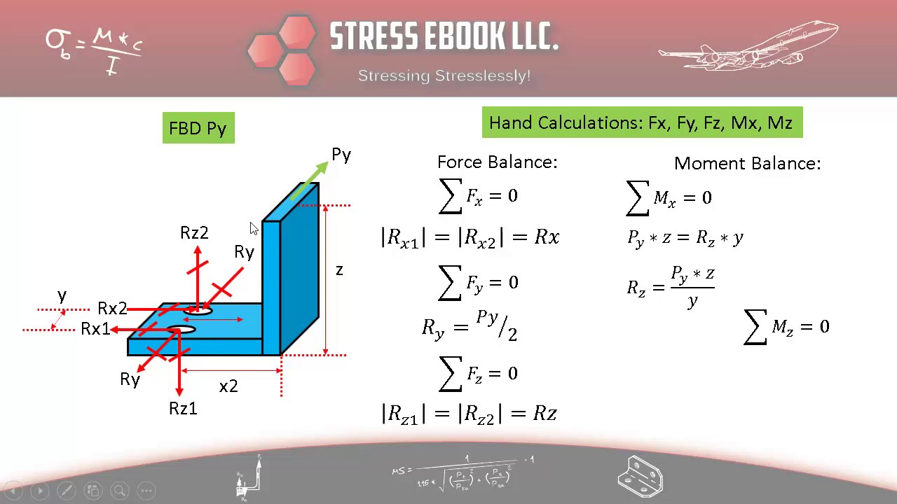
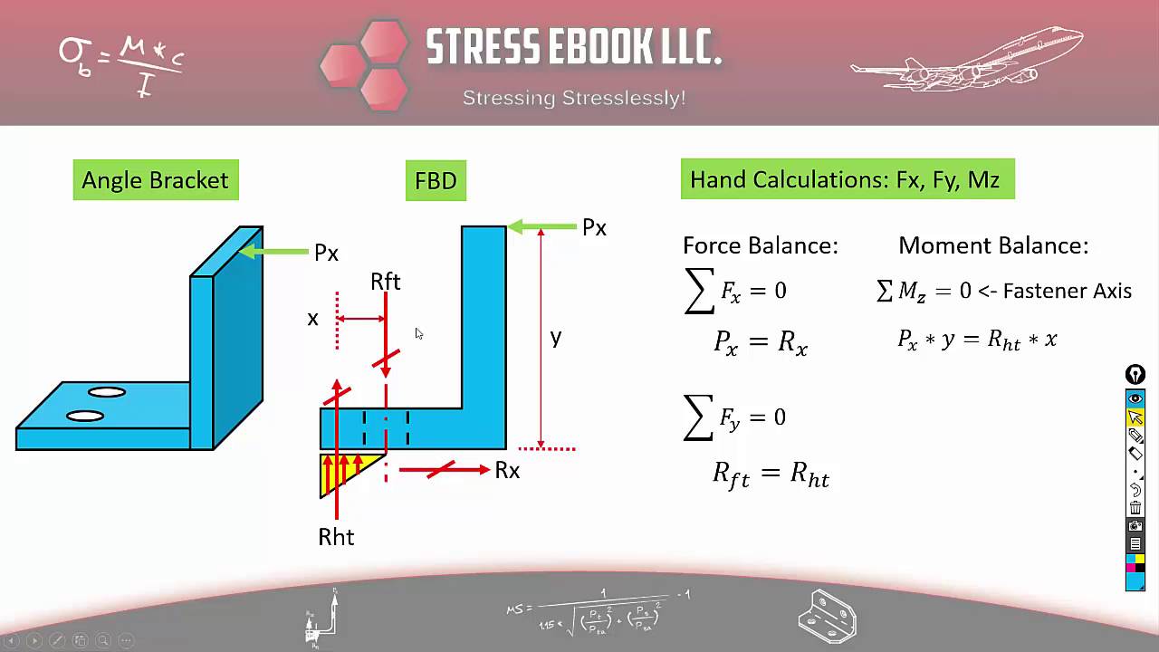
Angle Bracket Sizing And Stress Analysis Stress Ebook Llc
Pull Away Load On L Bracket Top Leg Hand Calculation Finite Element Analysis Fea Engineering Eng Tips
Angle Bracket Horizontal Load Heel Toe Youtube

Mechanical Engineering Ch 11 Friction 8 Of 47 Bracket On A Pipe Youtube
Mechanical Design Tutorials On Basic Calculations Bright Hub Engineering

Angle Bracket Sizing And Stress Analysis Stress Ebook Llc
0 comments
Post a Comment